
I decided to build an AND gate from discrete components. I used this (https://www.electronics-tutorials.ws/logic/logic_2.html) extremely helpful page as a guide.
Here is the schematic:

Basically, here’s how it works. If Input A is low (the switch is open so the input is pulled down to ground by the pull down resistor R4), Q1 is off since no current is flowing into its base. Therefore current does not flow to the output, which is pulled low by R3.
The same with Input B.
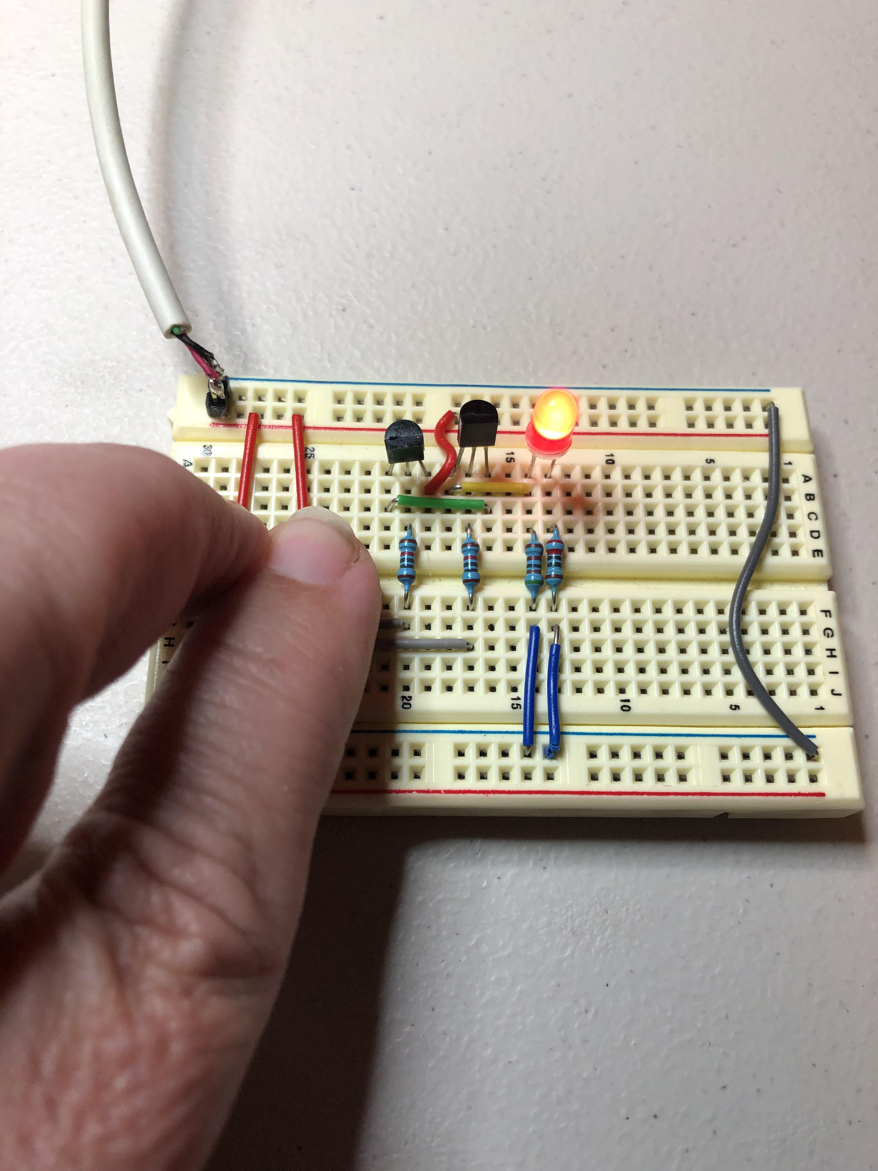
But if both buttons are pressed, both inputs are high, and both transistors are on, so current flows from +5 to the LED.
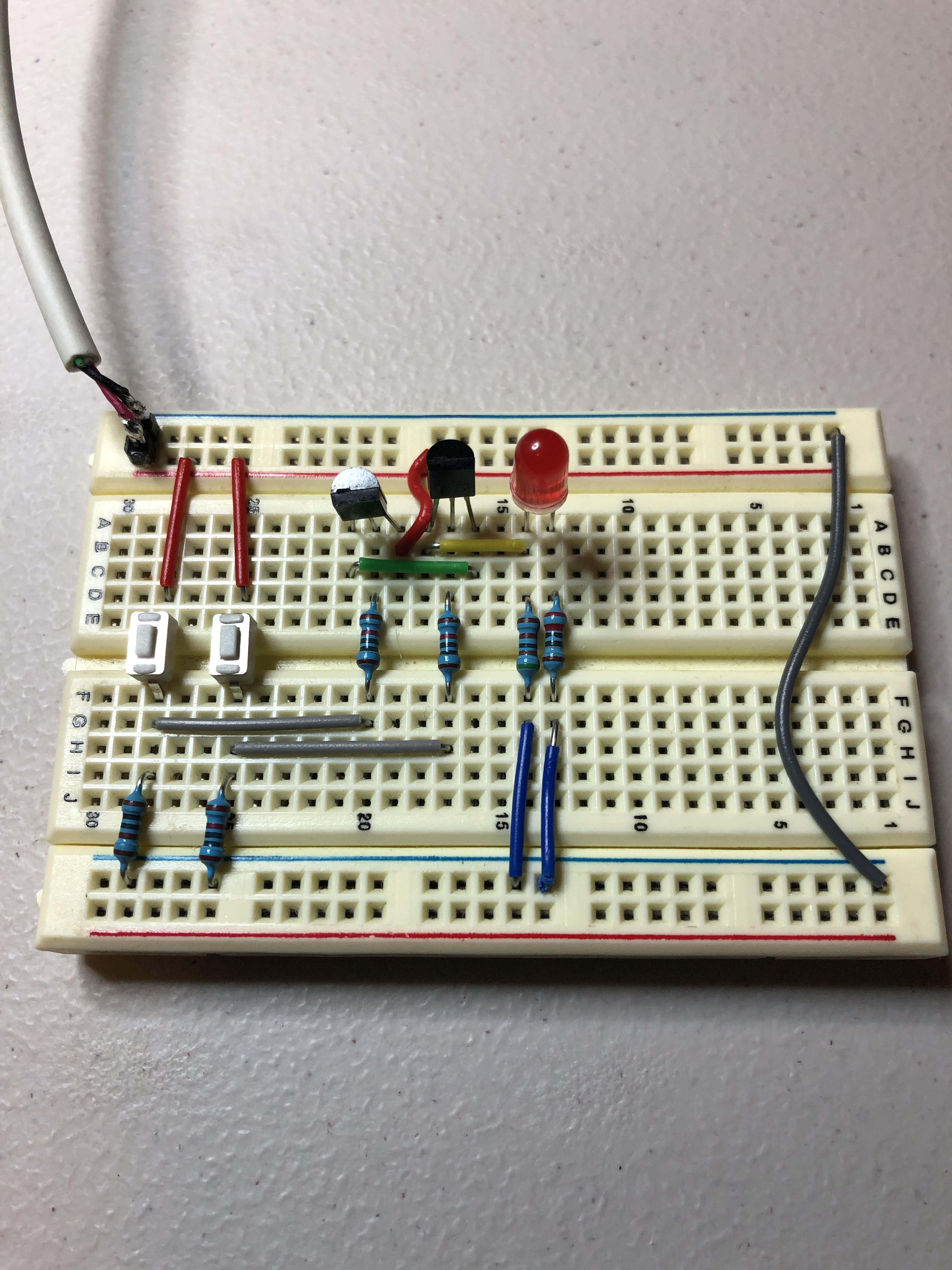
Here is the breadboard design:

Here is the device, with no buttons pushed:
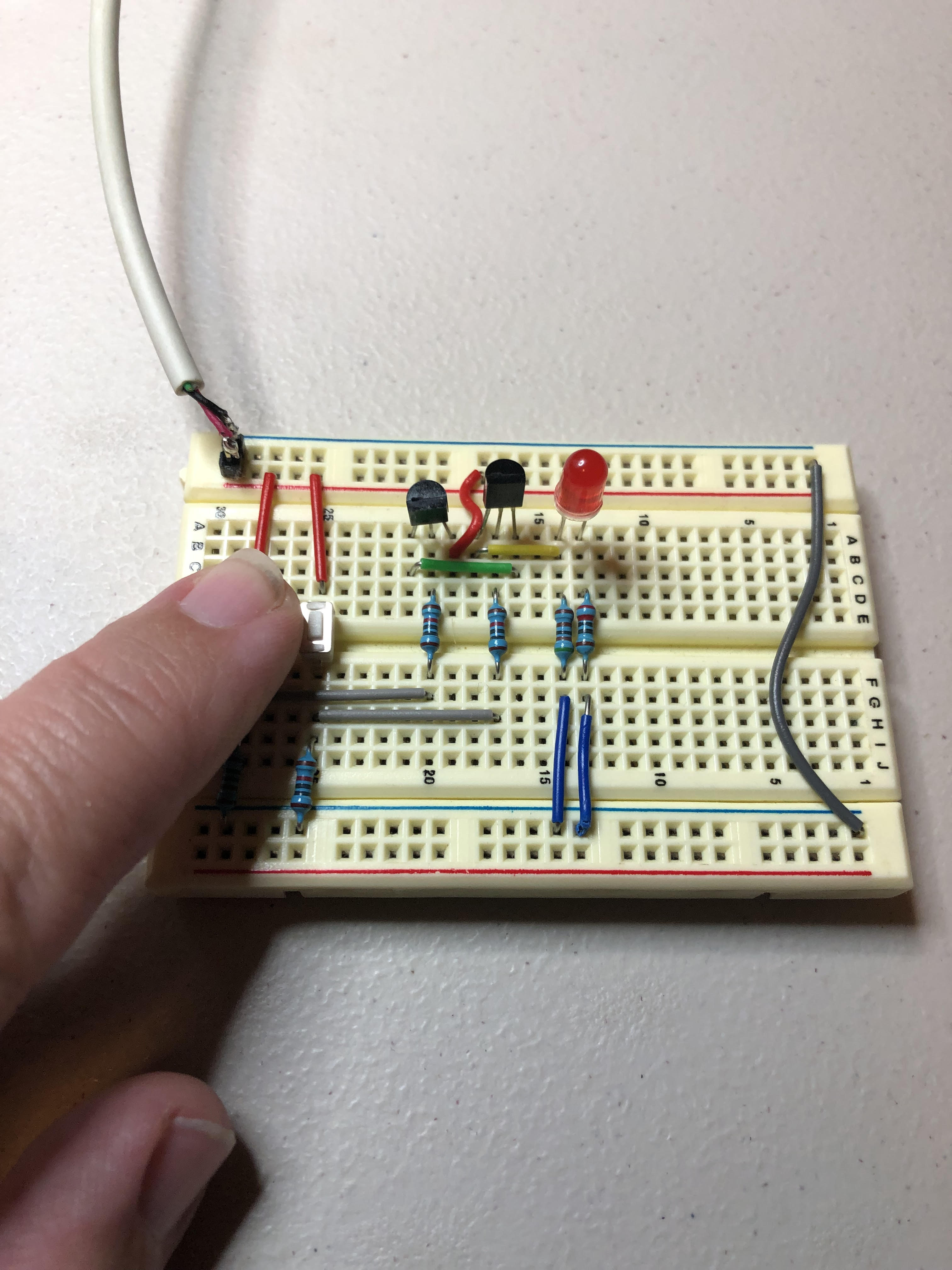
Here is the device with button one pushed:
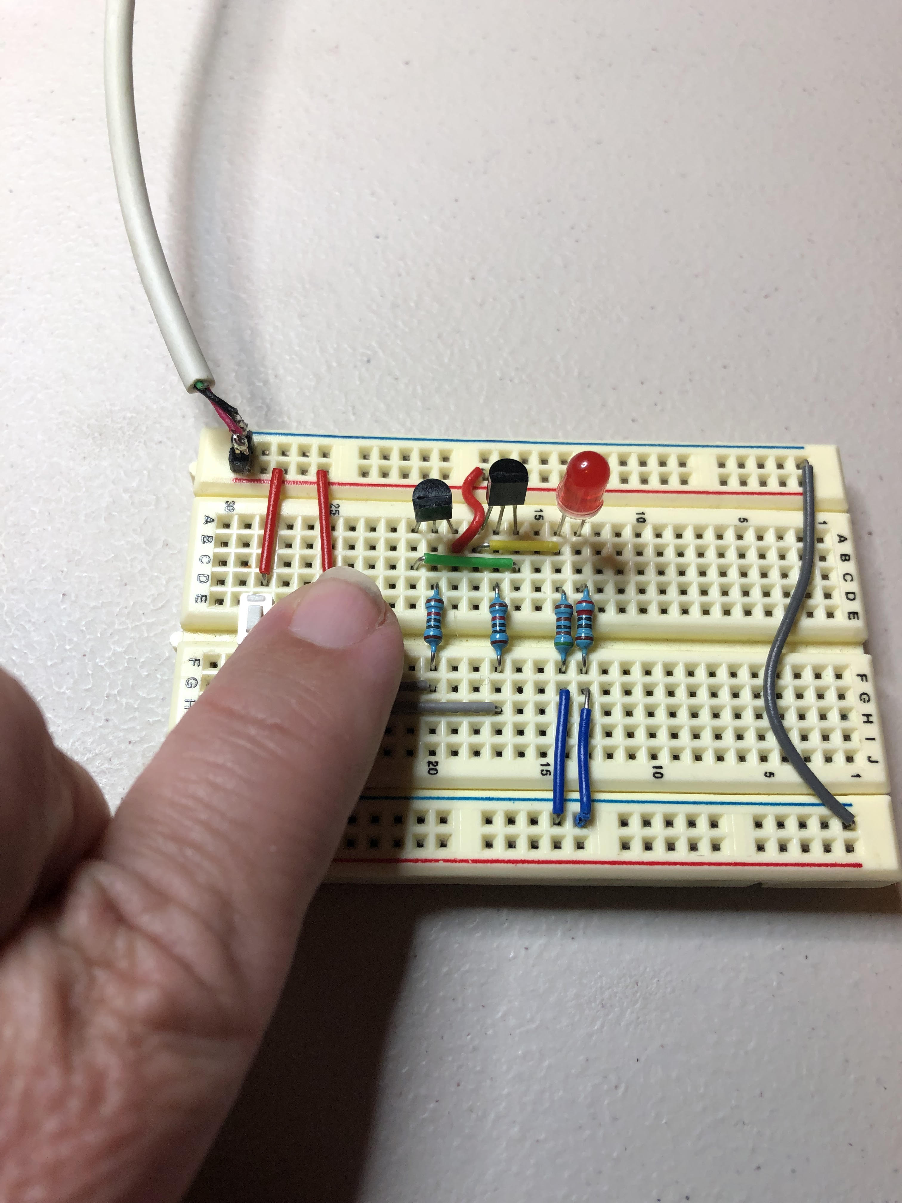
Here is the device with button two pushed:
Here is the device with both buttons pushed, i.e. the AND gate activated:
And that’s all …
